Comments
No comments yet. You can be the first!
Most popular documents in this category


Content extract
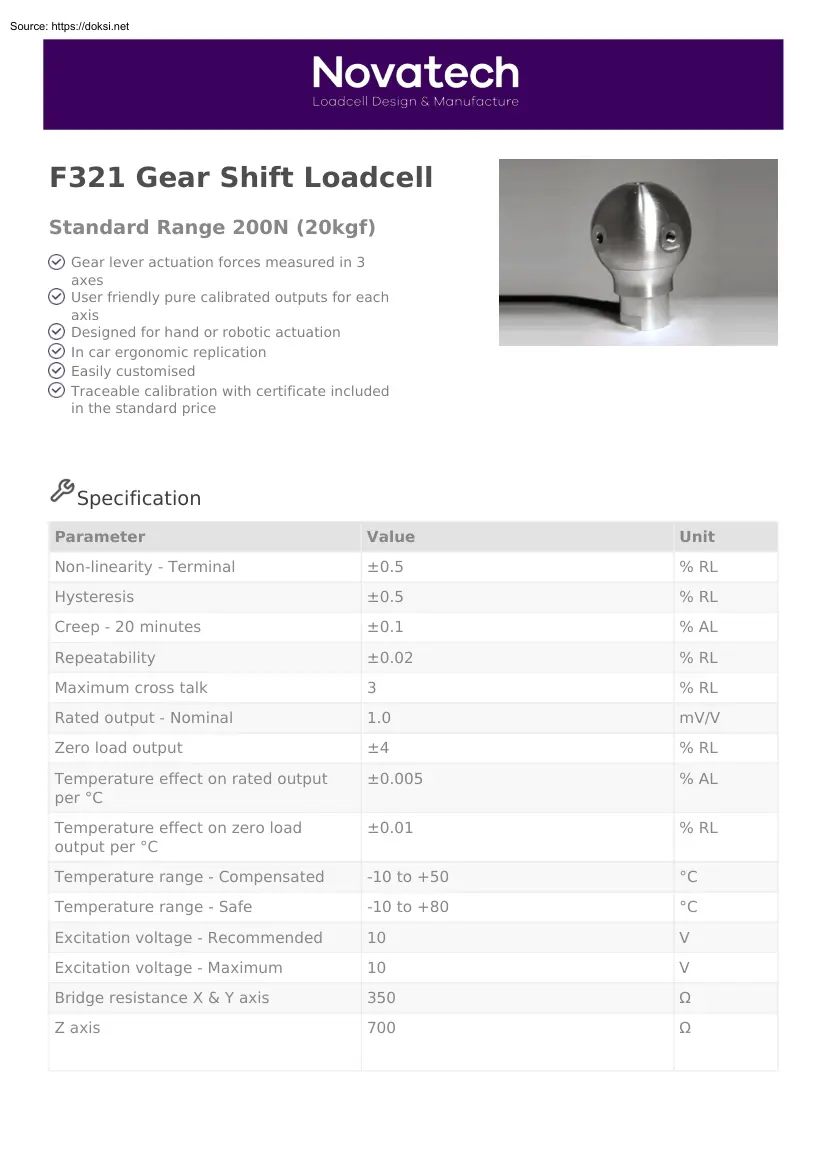
F321 Gear Shift Loadcell Standard Range 200N (20kgf) Gear lever actuation forces measured in 3 axes User friendly pure calibrated outputs for each axis Designed for hand or robotic actuation In car ergonomic replication Easily customised Traceable calibration with certificate included in the standard price Specification Parameter Value Unit Non-linearity - Terminal ±0.5 % RL Hysteresis ±0.5 % RL Creep - 20 minutes ±0.1 % AL Repeatability ±0.02 % RL Maximum cross talk 3 % RL Rated output - Nominal 1.0 mV/V Zero load output ±4 % RL Temperature effect on rated output per °C ±0.005 % AL Temperature effect on zero load output per °C ±0.01 % RL Temperature range - Compensated -10 to +50 °C Temperature range - Safe -10 to +80 °C Excitation voltage - Recommended 10 V Excitation voltage - Maximum 10 V Bridge resistance X & Y axis 350 Ω Z axis 700 Ω Insulation resistance - Minimum at 50Vdc 500 MΩ Structural stiffness -
Nominal - X & Y axis 2.0 x 10⁶ N/m Z axis 1.3 x 10⁶ N/m Overload - Safe 50 % RL Overload - Ultimate 100 % RL Weight - Nominal (excluding cable) 150 g The F321 gear shift loadcell measures gear lever forces required to achieve gear selection. An ergonomically designed gear knob senses the force from a human hand or a mechanical actuator. The three axis force components are represented by three pure loadcell output signals. The gear shift loadcell is supplied calibrated and ready to use, no in-situ calibration or mathematical computation is required. Easy fitment is achieved with mechanical axis referencing and simple attachment to a male thread or adapter. The gear shift loadcell, like all our automotive products, can be produced for environmental test chamber temperature requirements of -40 to 80°C. We are happy to design variants of this loadcell to meet your specific requirements. Please consult our engineering department. Order Codes Code Description
F321UF0000 Bi-directional, unrationalised Notes AL = Applied load. RL = Rated load. Temperature coefficients apply over the compensated range. Values apply to all axes unless otherwise specified. Connections The F321 is fitted with 2 metres of PVC insulated 12 core screened cable type 7-1-12C. The screen is not connected to the loadcell body. Function Wire Colour Excitation + Excitation Signal + Signal Screen X axis Red Blue Yellow Green Orange (thick) Y axis Violet Black Brown White Z axis Orange Turquoise Pink Grey Files Type Title Download STEP File F321UF0000 200N (200kgf) Download Outline Novatech Measurements Limited 83 Castleham Road, St Leonards on Sea, East Sussex, TN38 9NT, England. Telephone: +44 (0)1424 852744 Fax: +44 (0)1424 853002 E-mail: info@novatechloadcells.couk Powered by TCPDF (www.tcpdforg)
 When reading, most of us just let a story wash over us, getting lost in the world of the book rather than paying attention to the individual elements of the plot or writing. However, in English class, our teachers ask us to look at the mechanics of the writing.